-
Chengli Automobile Industry Park
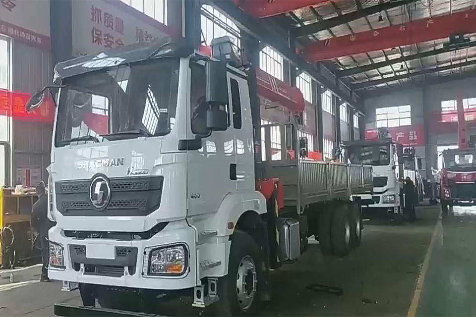
Design and analysis of hinge points of telescopic cylinder of box-type crane
Design and Analysis of Hinge Points for Telescopic Cylinders in Box-Type Cranes
Do you want to make your crane’s telescopic cylinder last longer? You need to think about the hinge points. The right design can help your crane work better and save you money on repairs.
Let’s look at how to make your crane’s telescopic cylinder work better. We’ll use simple words and share helpful tips.
Table of Contents
Why Telescopic Cylinder Hinge Design Matters
Cranes need strong telescopic cylinders to lift heavy loads. But these cylinders often break too soon. Why? The main reason is radial force. This happens when the crane arm bends under weight and pushes on the cylinder from the side.
Most crane makers use reverse support structures. This means:
- The piston rod stays fixed to the base arm
- The cylinder tube moves with the second arm
- This makes the cylinder more stable
But there’s still a problem – when the arm bends, it can push on the cylinder and cause damage.
The Long Oval Hole Solution
Smart crane designers use a long oval hole at the hinge point. This clever design:
- Lets the cylinder move up and down without stress
- Helps the cylinder last much longer
- Prevents damage from side forces
The long oval hole works with a roller support at the cylinder end. Together, they make sure the cylinder only feels pulling and pushing forces, not harmful side forces.
How to Calculate the Right Design
To make the best hinge point, you need to know how much the arm will bend. Here’s what happens:
- The crane arm bends when lifting heavy loads
- This bending pushes on the cylinder
- We need to calculate this bending to make the right size oval hole
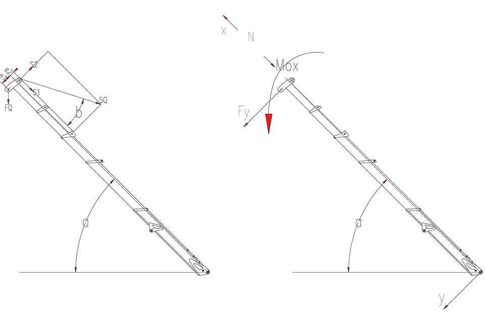
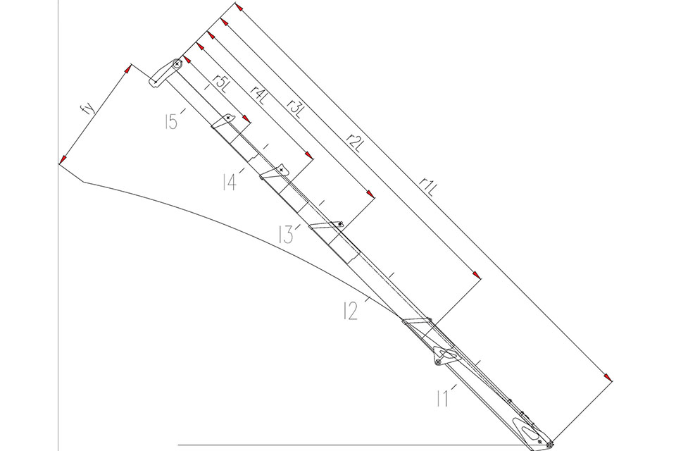
Calculating Total Arm Deflection
The total deflection (bending) has two parts:
- Bending from the load (f_wy)
- Bending from gaps between arm sections (f_jy)
So: Total deflection = f_wy + f_jy
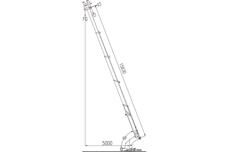
Real-World Example: 5-Ton Box-Type Crane
Let’s look at a real example:
| Parameter | Value |
|---|---|
| Maximum lifting capacity | 1,200 kg (12 kN) |
| Arm self-weight | 1,300 kg (13 kN) |
| Arm length (extended) | 15.63 m |
| Arm angle | 69° |
| After doing all the math (which includes lots of formulas), we found: |
- Bending deflection (f_wy): 359.48 mm
- Joint gap deflection (f_jy): 94.67 mm
- Total arm deflection: 454.15 mm
This means the arm tip moves down almost half a meter when fully loaded!
Telescopic Crane Cylinder Hinge Design & Analysis
| Parameter | Value |
|---|---|
| Max Lifting Capacity | 1,200 kg (12 kN) |
| Arm Self-Weight | 1,300 kg (13 kN) |
| Arm Length (Extended) | 15.63 m |
| Total Arm Deflection | 454.15 mm |
How This Affects the Hinge Point
Using these numbers, engineers calculated that the hinge point needs a long oval hole of about 64 mm to prevent harmful side forces on the cylinder.
Important Design Considerations
When designing your mobile crane telescopic cylinder hinge points:
- Make the right size oval hole
- Too short: Won’t allow enough movement
- Too long: Might weaken the structure
- Add roller supports
- Put them at the cylinder head to balance weight
- This prevents three-point bending problems
- Consider all load cases
- Calculate deflection for the worst-case loads
- Include both arm bending and joint gaps
- Think about cylinder stability
- The reverse support design helps stability
- The cylinder length-to-diameter ratio matters
Design Tips for Better Performance
Want your crane truck to work better? Follow these tips:
- Design the base arm with slight upward curve to counter self-weight deflection
- Use thicker slide blocks at the end of each arm section
- Set the right clearance between arm sections (usually 1-3 mm)
- Position the cylinder hinge close to the section where relative movement occurs
- Calculate deflection carefully using the formulas shown in the tables
Practical Design Table for Hinge Points
| Arm Length | Recommended Oval Hole Length | Support Roller Position |
|---|---|---|
| Under 10 m | 30-40 mm | Near cylinder head |
| 10-15 m | 40-60 mm | At cylinder end |
| Over 15 m | 60-80 mm | At cylinder end with reinforcement |
Final Thoughts
The right hinge point design makes your crane’s telescopic cylinder last much longer. By using a long oval hole and the right support structure, you can make sure your cylinder only feels the forces it’s built to handle.
For crane operators and designers, this means:
- Less downtime for repairs
- Lower maintenance costs
- Better crane performance
- Safer lifting operations
When designing or buying your next material handling vehicle, pay special attention to how the telescopic cylinder connects to the arm. The right design will save you money and keep your crane working well for years.
Remember: the goal is to let the cylinder push and pull, not bend!